GNSS Reference Station Installation: Antenna, Power & NTRIP
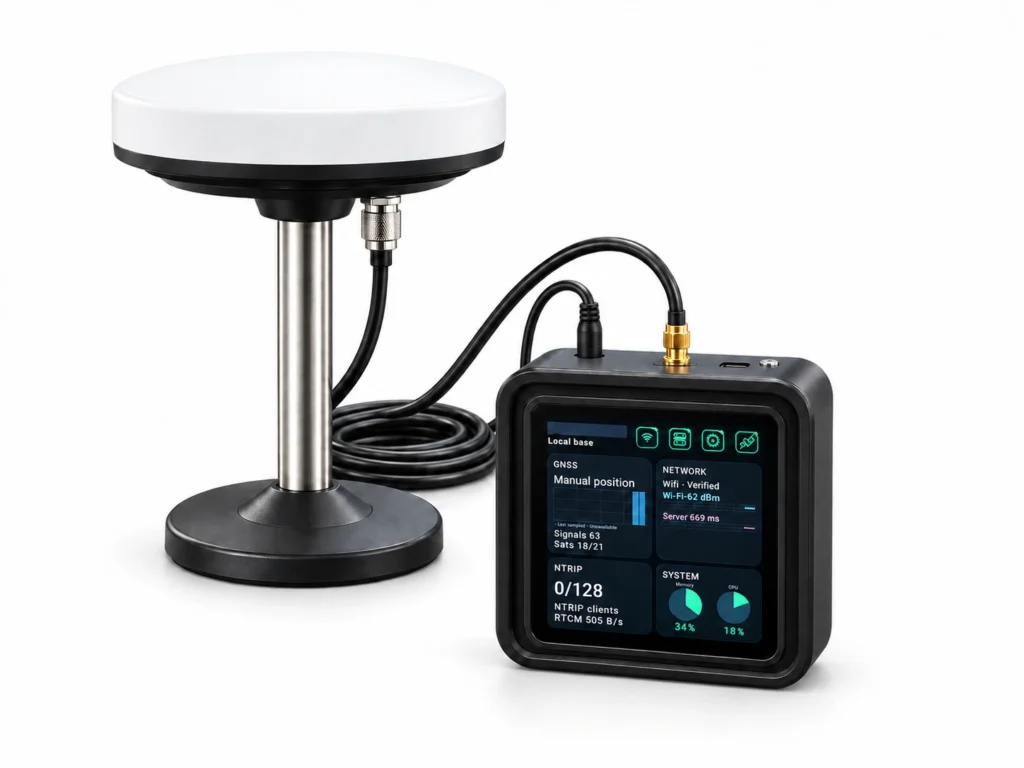
Install a fixed GB30 GNSS reference station with the antenna outdoors and the main unit indoors. Plan stable mounting, SMA antenna cabling, DC power, reference coordinates and correction-service acceptance checks.
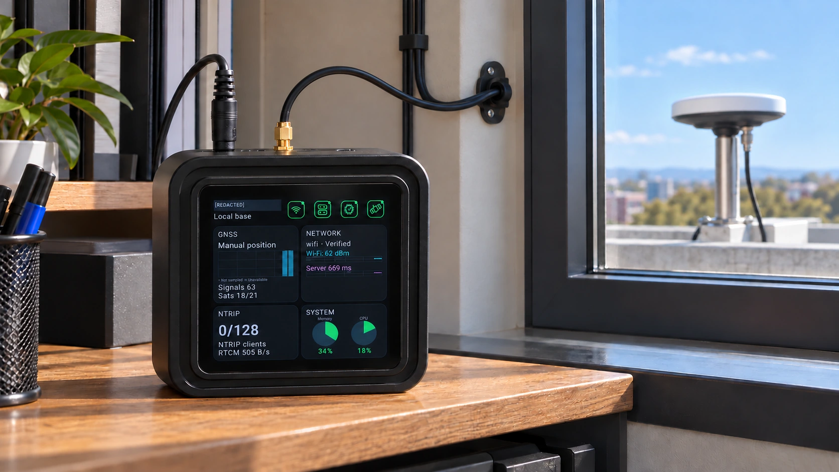
A practical guide to positioning the outdoor antenna, protecting the indoor GB30 and checking the full reference-to-field workflow.
Begin with a stable reference point
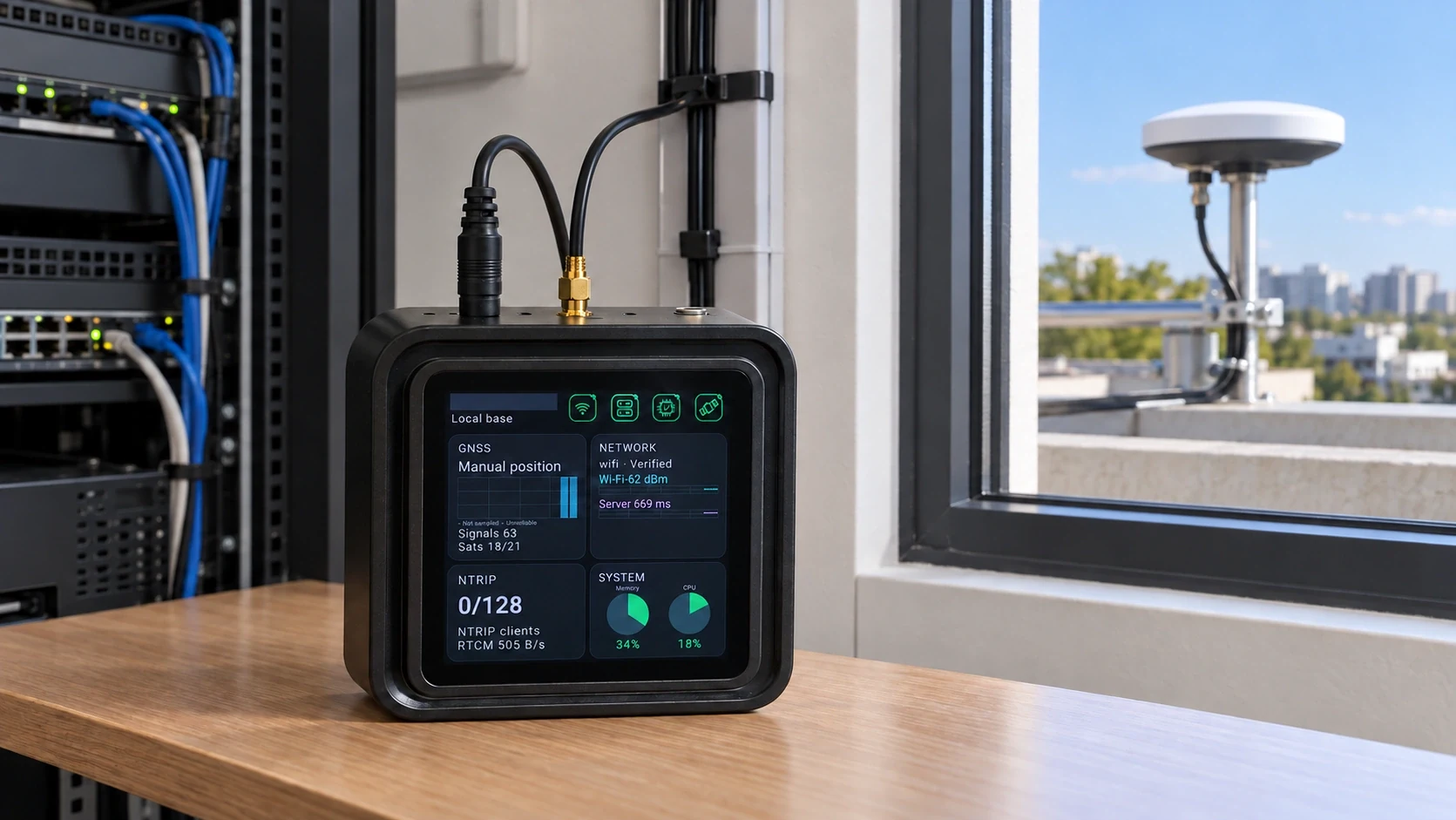
Keep the GB30 main unit fixed indoors, with the GNSS reference antenna fixed outdoors at a stable location and with a clear sky view. The complete reference kit includes the main unit, external GNSS antenna, antenna mounting stand and coaxial cable. Building works, additional mounting hardware and separate power requirements should be agreed in the quotation.
Route the coax to the SMA input
Connect the outdoor antenna coaxial cable to the gold SMA antenna input on the main unit. Connect the DC supply to its round power input. Leave USB-C disconnected in normal operation: it is for debugging. Confirm the cable length, connector requirements, cable protection and the installation route for the site.
Establish the coordinate reference
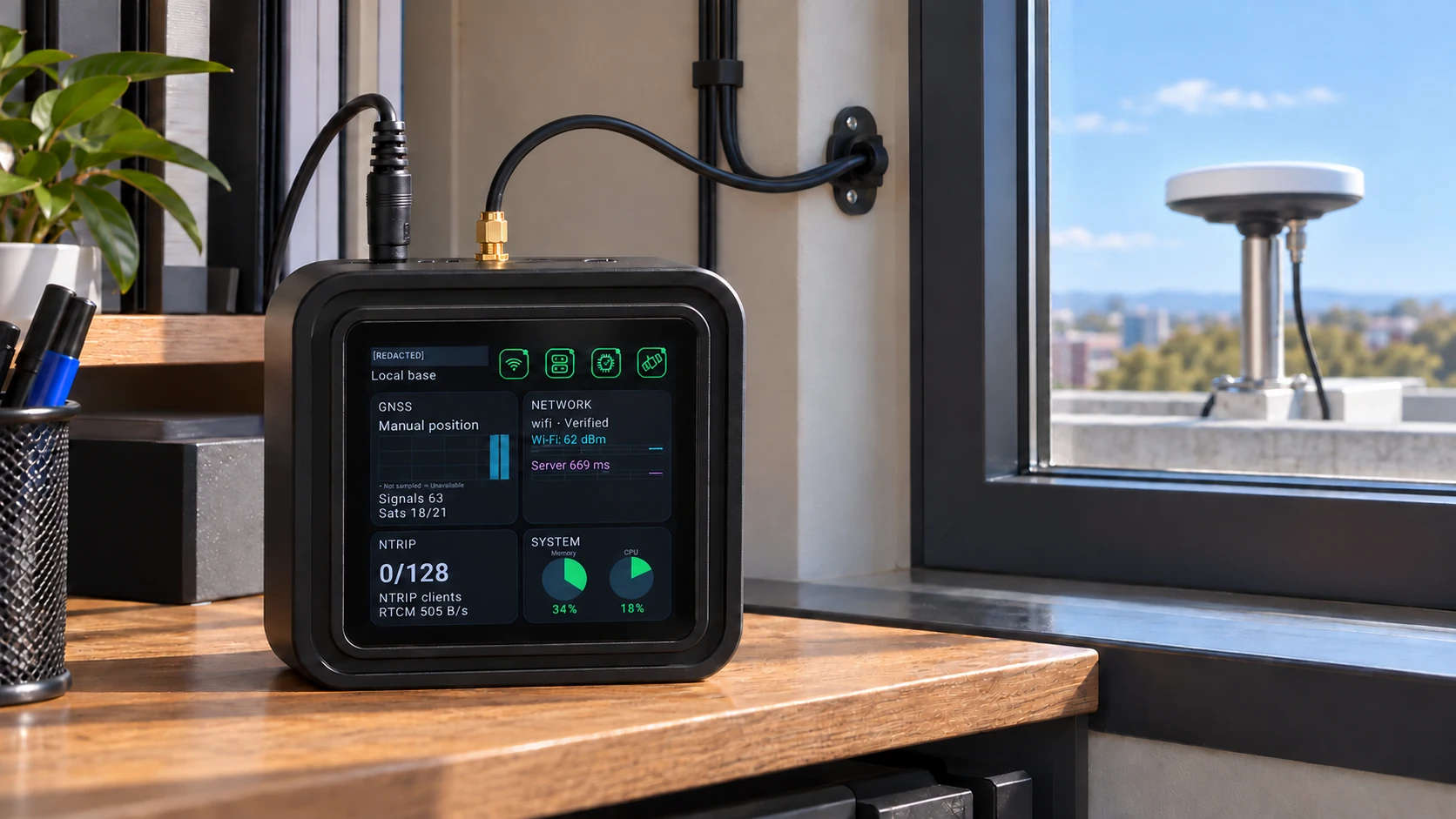
Choose known fixed coordinates or a suitable survey-in workflow according to the project requirements. Verify the reference frame, height convention and antenna reference before accepting the base position. A convenient antenna location does not by itself establish a valid project reference.
Configure the station role and network
Local Base Station mode provides the local source and an active Caster. Uplink Base Station mode uploads an independent source to a bound Caster and disables its own Caster. Choose the correct role for each site, then verify network reachability and the intended direct NTRIP or tunnel path.
Verify using the intended client
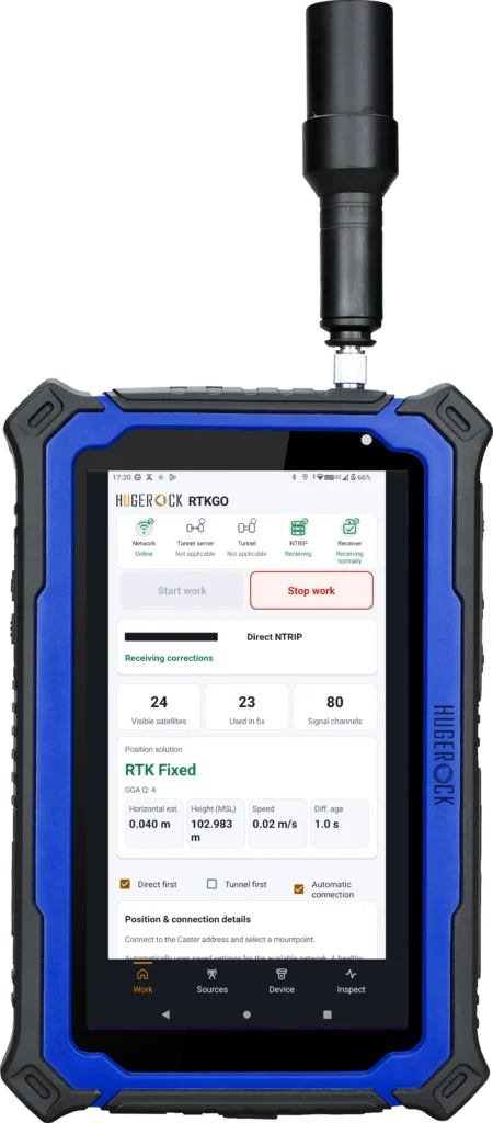
Use a compatible rover, industrial RTK terminal or field device to test the accepted mountpoint. Inspect reference identity, correction reception, age and receiver solution status. Validate observations against independent check points and the project tolerance.
Hand over a repeatable installation
Record antenna setup, base coordinates, source identifiers, network settings and acceptance observations. GB30 typical and full-load figures are 1.5W and 2W for the main unit; assess external equipment separately. A useful handover lets the next operator reproduce the accepted reference workflow.
Installation checks before accepting the reference service
Where should the GB30 main unit and antenna be installed?
Keep the GB30 main unit in a protected indoor position. Fix the GNSS antenna outdoors at a stable reference location with a clear sky view, and route the coaxial cable to the main unit SMA input.
Why are reference coordinates part of installation acceptance?
A stable antenna does not establish the correct reference coordinates by itself. Confirm the antenna reference, coordinate frame and reference position, then validate rover observations against independent check points.
Related: GB30 GNSS base + NTRIP Caster kit · GB30 installation and technical support · Survey reference deployment workflow