GB30 main unit
Local GNSS reference source and integrated NTRIP Caster in Local Base Station mode. Fixed indoor installation.
 RTKGO
Request a quote ↗
RTKGO
Request a quote ↗
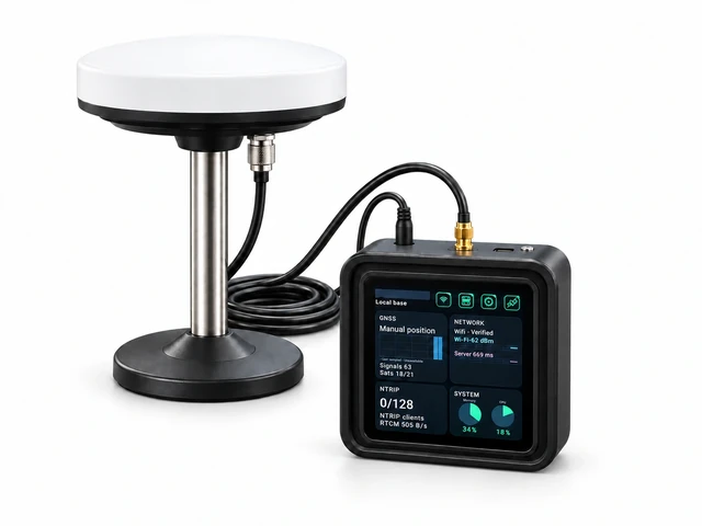
Product views and installation illustrations. Fix GB30 indoors and the GNSS antenna outdoors. Normal operation uses DC power and the SMA antenna feed; USB-C is for debugging only.
Create and distribute RTK corrections from one low-power ARM device. In Local Base Station mode, GB30 combines its own GNSS reference source with an NTRIP Caster. The complete kit includes the main unit, external GNSS antenna, antenna stand and coaxial cable.
Project-specific quotation · Configure your GB30 deployment
Network tunnel: no public IP, port forwarding or dedicated line. Internet access and a compatible client are required.
Generate the source. Distribute corrections. Connect professional RTK equipment.
Outdoor GNSS antenna.
Indoor GB30, with DC power and the antenna coax on its SMA input. USB-C is for debugging only.
Its own local source, plus up to eight independent uplink reference sources.
Explore the platform →Handhelds, rovers, machine terminals, robotics and other RTK industry devices.
Choose a field device →Network tunnelling requires internet access and a compatible client.
Local GNSS reference source and integrated NTRIP Caster in Local Base Station mode. Fixed indoor installation.
A fixed outdoor reference antenna with a clear sky view. Agree the antenna position and reference coordinates.
Specify the mounting location and any additional building or roof installation hardware.
Route to the existing top-edge SMA antenna connector. Confirm cable length and connector requirements.
Power supply, network access, building works, any additional installation equipment, field receivers and application licences are specified separately. Confirm the final included items in your quotation.
Generate your own reference data and serve clients from the same GB30. Add independent sources from up to eight uplink GB30 stations.
An 8 + 1 layout provides nine reference points. Approximately 10km station spacing is a planning example; actual coverage requires site validation.
Sources are not fused. Nearby source selection does not imply automatic roaming, VRS or guaranteed coverage.
Use these application examples to define the site, reference source, field software and installation requirements for your quotation.
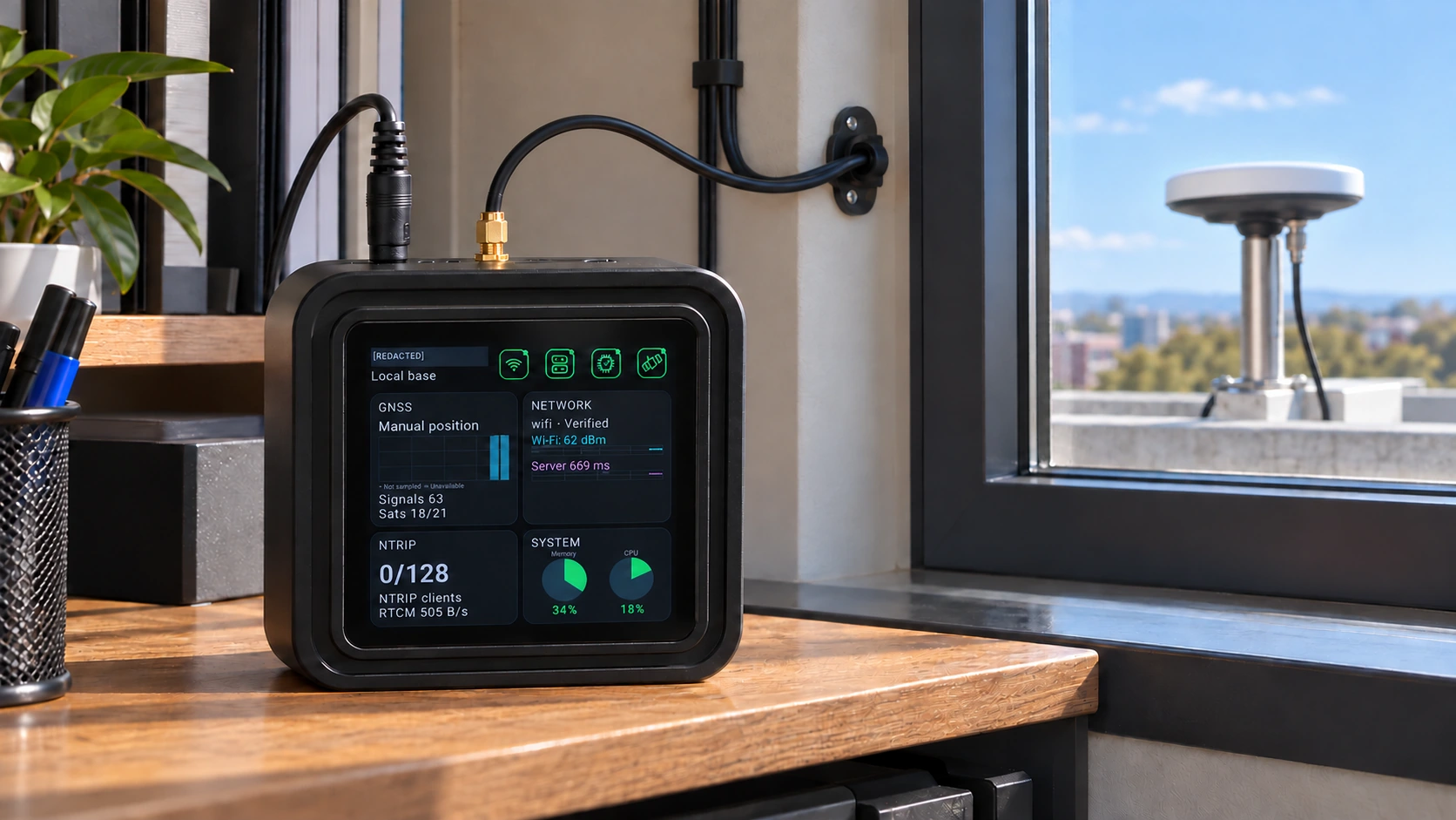
Keep the main unit indoors, with a fixed outdoor GNSS antenna. Serve a validated reference source to compatible survey clients.
Discuss this application ↗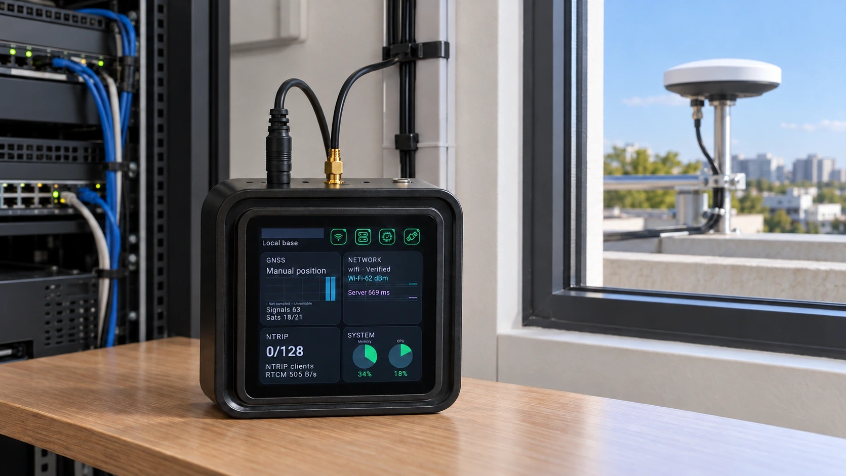
Plan antenna cable routing from the roof or exterior mount to the indoor SMA input. Verify power, network and handover records.
Discuss this application ↗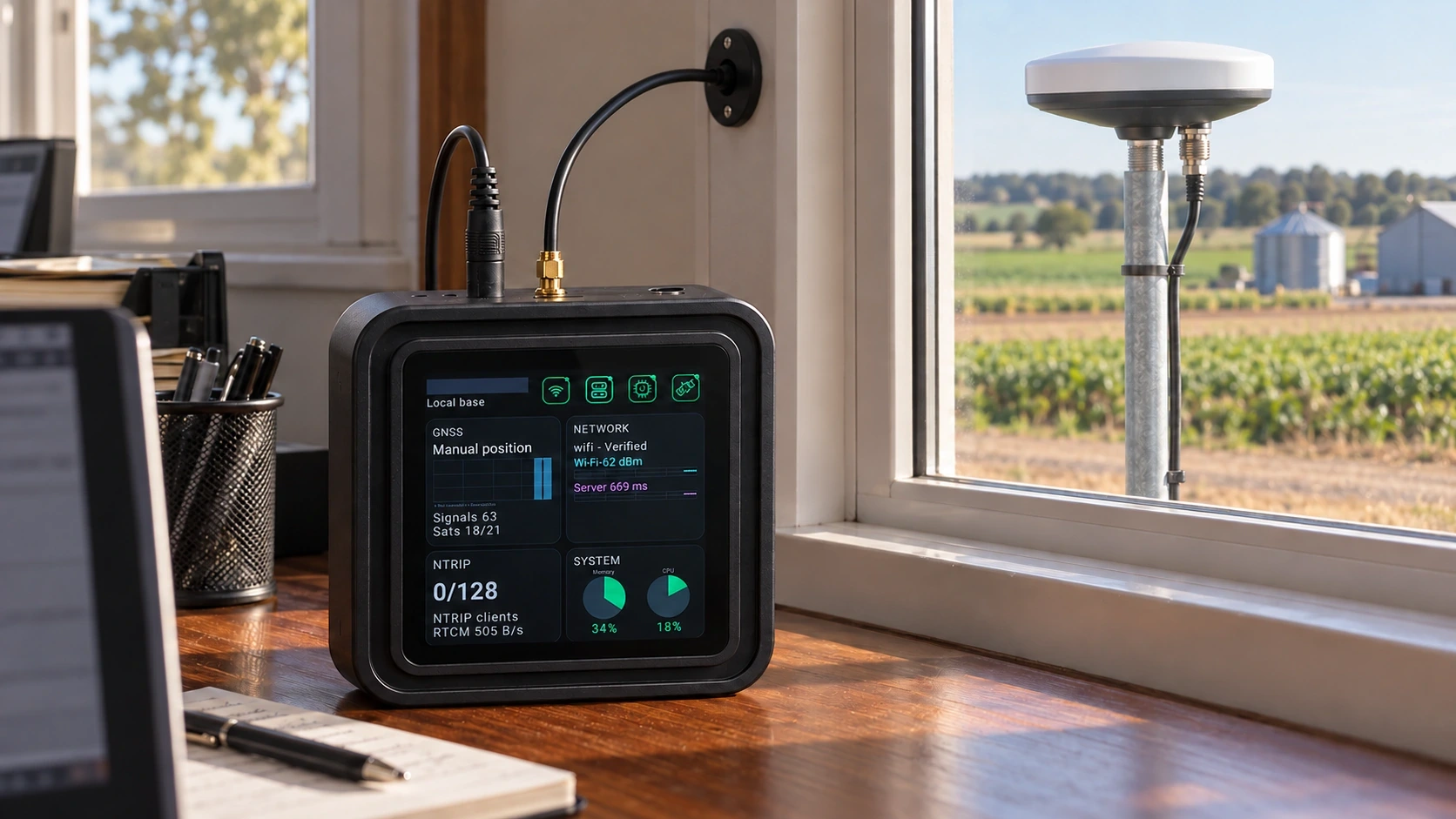
Install a stable reference point at the service building. Validate the correction path for compatible agricultural terminals.
Discuss this application ↗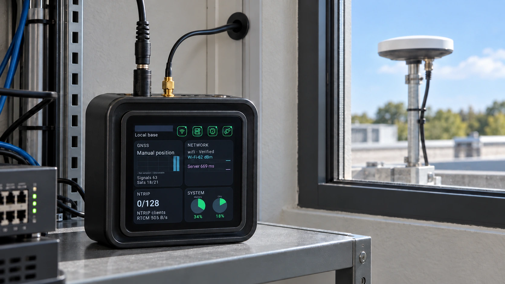
Keep the reference infrastructure indoors while compatible vehicles or outdoor robots use the selected source. Validate integration for the site.
Discuss this application ↗Review receiver status, network connectivity, reference sources and client sessions from the GB30 interface.
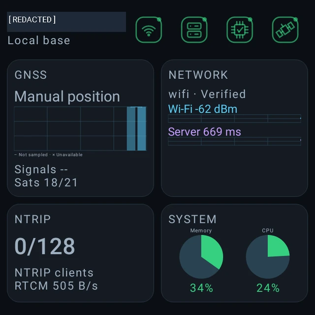
GNSS, network, NTRIP and system information in one view. Check live details before accepting a handover.
The standard client limit is 256. Displayed connection counts reflect the active device configuration.
Read the complete user guide →A fixed reference point begins with the right installation.
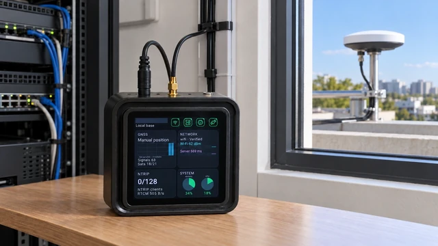
Mount the GNSS antenna outdoors at a stable reference location with a clear view of the sky.
Connect the DC supply to the round power input and the antenna coax to the gold SMA input. Leave USB-C disconnected during normal operation; it is for debugging only.
Connect to an available network, choose the operating role, then check source and client status.
Choose the path for your network environment, client compatibility and intended capacity.
Connect compatible industrial RTK devices through a direct NTRIP connection.
Connect through a tunnel where a dedicated public network setup is unavailable.
GB30 integrates the local reference and Caster roles. Compare the complete hardware, power, network and maintenance scope for your project.
| Decision point | GB30 integrated approach | Separate base + PC / server Caster | Separate base + hosted Caster |
|---|---|---|---|
| Hardware scope | Local base + Caster in one ARM device | Receiver / base plus a separate computing host | Receiver / base plus a hosted service |
| Power scope | 1.5W typical / 2W full load for GB30 | Include the base and selected host | Include the base; service infrastructure is external |
| Network setup | Tunnel avoids a dedicated public IP and port forwarding | Depends on server location and access architecture | Depends on the service and source-upload method |
| Operating cost | Device, network, installation and any service terms | Base, host, software, network and maintenance | Base, network and provider service terms |
| Capacity | Default 256; up to 4,000 direct NTRIP clients under the configured policy | Validate the selected software and host | Check provider policy and service limits |
Power figures cover GB30; account separately for external antennas, network equipment and other installation loads.
Start with one local base / Caster. Add uplink reference points where the project needs independent sources.
Energy = units × 1.5W × 8,760 hours / 1,000. This is a calculation at continuous typical load; external antenna and other unspecified loads are excluded. Capacity belongs to the central Caster and is not multiplied by the number of stations.
Carry this plan into an enquiry ↗Each GB30 kit includes the main unit, external GNSS antenna, mounting stand and coaxial antenna cable. Confirm cable length, mounting requirements, separate power needs, installation, network, service terms, tax and freight. Request a project-specific quotation for the complete deployment scope.
| Product role | Integrated GNSS local reference base + NTRIP Caster |
|---|---|
| Included in each complete kit | GB30 main unit; External GNSS antenna; Antenna mounting stand; Coaxial antenna cable |
| Computing platform | Low-power ARM processor |
| Local Base Station mode | Own reference source and active Caster; accepts independent uplink sources |
| Uplink Base Station mode | Uploads an independent local source to a bound Caster; its own Caster is disabled |
| Default client policy | 256 simultaneous client terminals |
| Default uplink allowance | 8 uplink reference stations |
| Available reference sources | 1 local reference source + up to 8 independent uplink reference sources |
| Maximum direct NTRIP clients | Up to 4,000 simultaneously online; a raised limit/configuration is distinct from the default policy |
| Network tunnel | No dedicated public IP, port forwarding or dedicated line required; internet access and a compatible client remain necessary |
| Tunnel capacity | Confirm for the selected deployment; the direct NTRIP maximum does not apply |
| Network setup | Wi-Fi configuration through Android settings; network options depend on the ordered configuration |
| Reference coordinates | Survey-in or known fixed coordinates; verify reference frame, height type and antenna reference |
| Source access | NTRIP sourcetable discovery and mountpoint selection; local and uplink sources remain separate |
| Initial pairing | Six-digit code valid for 15 minutes; a valid binding survives code expiry |
| Monitoring interface | Touchscreen; GNSS, network, NTRIP and system cards; clients and uplink sessions monitored separately |
| Configuration management | Mode-specific profiles; save settings and apply them to the device |
| Typical / full-load power | 1.5W / 2W |
| Energy at continuous typical load | 13.14 kWh/device/year at 1.5W for 8,760 hours (calculated) |
| Antenna connection | Outdoor fixed GNSS antenna; coaxial cable connects to the main unit's SMA antenna input |
| Installation | Main unit fixed indoors with stable power; antenna fixed outdoors with clear sky |
| User guide version | English user guide 1.0.34; match configuration to installed firmware |
| Normal operating connections | DC round-input power + GNSS antenna coax on SMA. USB-C is for debugging only; leave it disconnected in normal operation. |
Input electrical rating and power supply · GNSS receiver, constellations, frequencies and output configuration · Dimensions, weight, operating temperature and protection rating · Antenna cable length and connectors, mounting requirements and separately specified power supply · Tunnel compatibility, capacity and service conditions · Shipping firmware, client policy and access configuration.
Confirm the required client capacity, firmware, power supply and installation accessories when requesting your configuration.
Match the reference setup, network and field equipment before deciding quantities.
Yes. In Local Base Station mode it generates its own reference source and runs the Caster. The same Caster can also make independent accepted uplink sources available to clients.
The network tunnel avoids a dedicated public IP, port forwarding and a dedicated line. Ordinary internet access, service reachability and compatible clients remain necessary. Direct NTRIP needs a reachable service on the selected network path.
No. The standard configuration allows 256 client terminals and 8 uplink stations. Up to 4,000 simultaneous clients applies to direct NTRIP under the configured policy. Confirm the client limit and load conditions for your project.
The hub exposes separate local and uplink sources. Select the appropriate nearby source for the work area. This deployment uses independent reference streams; choose and validate a mountpoint for each work area.
The normal installation keeps GB30 fixed indoors with stable power. Mount the GNSS antenna outdoors, then route coax indoors to the existing SMA antenna connector.
Compatible NTRIP RTK handhelds, field tablets, rovers, agricultural and vehicle positioning terminals, robotic systems and other industrial RTK equipment. Verify protocol, data format, client configuration and tunnel compatibility as applicable.
Include the GB30 main unit, external GNSS antenna, antenna mounting stand and coaxial antenna cable. Confirm cable length, mounting requirements, power supply, network, tunnel/service terms, installation, tax, freight and support conditions separately.
Specify your sites, client count and network environment.
Install GB30 indoors and fix the GNSS antenna outdoors at a stable reference point. The central device distributes its own reference source and independent streams from uplink GB30 stations. Survey rovers and compatible industry terminals select the appropriate source for their work area.
The default policy supports 256 simultaneously online client terminals and eight uplink reference stations. The maximum is 4,000 simultaneous clients in direct NTRIP mode. Confirm the configured policy and network capacity for the deployment; this maximum is not a tunnel-capacity specification.
Network tunnel access does not require a public IP address, port forwarding or a dedicated line. Ordinary internet access, service reachability and compatible tunnel software remain necessary. Direct NTRIP uses a reachable Caster endpoint.
A typical layout uses one GB30 in Local Base Station mode and up to eight uplink GB30 reference stations. The central device distributes nine independent sources, including its own. Approximately 10km spacing is a planning example, not a guaranteed coverage radius or automatic nearest-station service.