Which connections are used during normal GB30 operation?
Normal operation uses the round DC power input and the GNSS antenna coaxial cable connected to the SMA input. USB-C is for debugging and remains disconnected during normal operation.
 RTKGO
Request a quote ↗
RTKGO
Request a quote ↗
Find installation guidance for a fixed GB30 GNSS reference station, check your correction-data connection, and download the selected RTK product specifications and user documentation.
A fixed reference point begins with the right installation.
Mount the GNSS antenna outdoors at a stable reference location with a clear view of the sky.
Connect the DC supply to the round power input and the antenna coax to the gold SMA input. Leave USB-C disconnected during normal operation; it is for debugging only.
Connect to an available network, choose the operating role, then check source and client status.
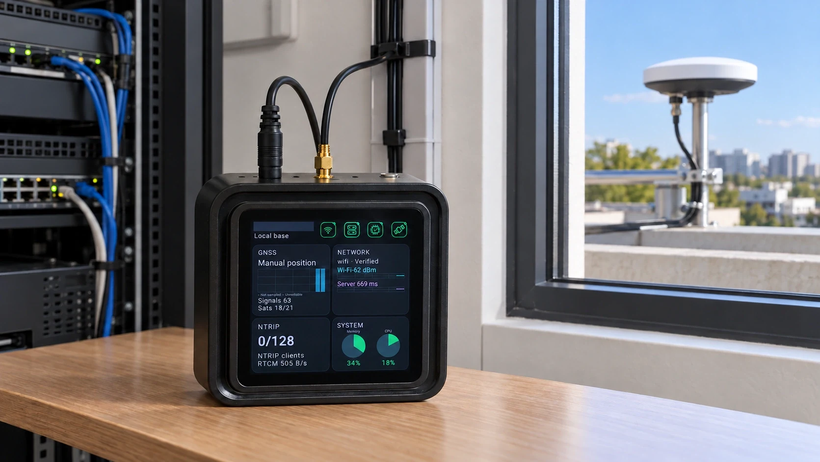
The GB30 main unit is normally fixed indoors. Install the GNSS antenna at a stable outdoor reference location, route its coaxial cable indoors, and connect it to the existing SMA antenna input.
It avoids a dedicated public IP, port forwarding and a dedicated line. Ordinary internet access, service reachability and a compatible tunnel client are still needed. The direct NTRIP maximum does not establish tunnel capacity.
Local Base Station mode combines an own reference source with an active Caster. Uplink mode provides an independent source from another reference point to that Caster. Sources remain separate.
Choose from G60M, G71M, G80M, G101M, GK101M and H81 RTK 5G-M60. Antenna, mounting, power and software options are specified in your quotation.
Fix the outdoor GNSS antenna at a stable point with clear sky visibility. Keep the GB30 main unit indoors, connect the antenna cable to the SMA input and use the round DC power input for normal operation. Establish reference coordinates and verify the correction stream before field acceptance.
Normal operation uses the round DC power input and the GNSS antenna coaxial cable connected to the SMA input. USB-C is for debugging and remains disconnected during normal operation.
Record the model and firmware, operating mode, Caster address and mountpoint, network path, receiver status and correction age. Check power, antenna, reference coordinates and service reachability before sharing the findings with support.