Vehicle RTK Positioning & Dual-Antenna GNSS Heading
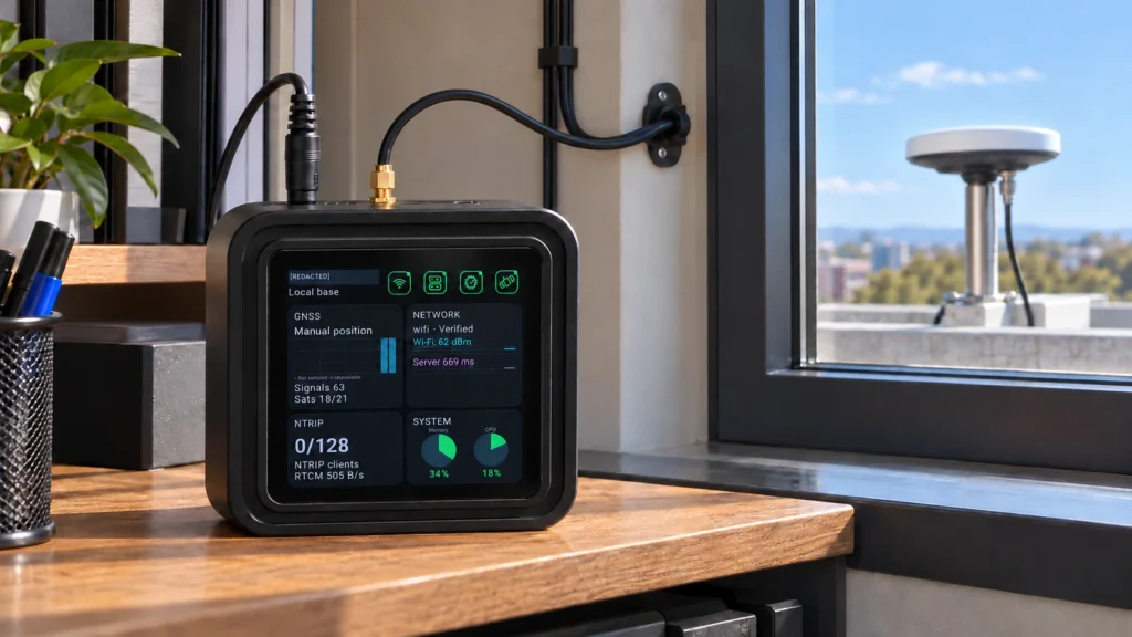
Integrate vehicle RTK positioning and dual-antenna heading with the GK101M terminal. Plan the GB30 correction source, external antenna pair, DC supply and machine-side data interfaces together.
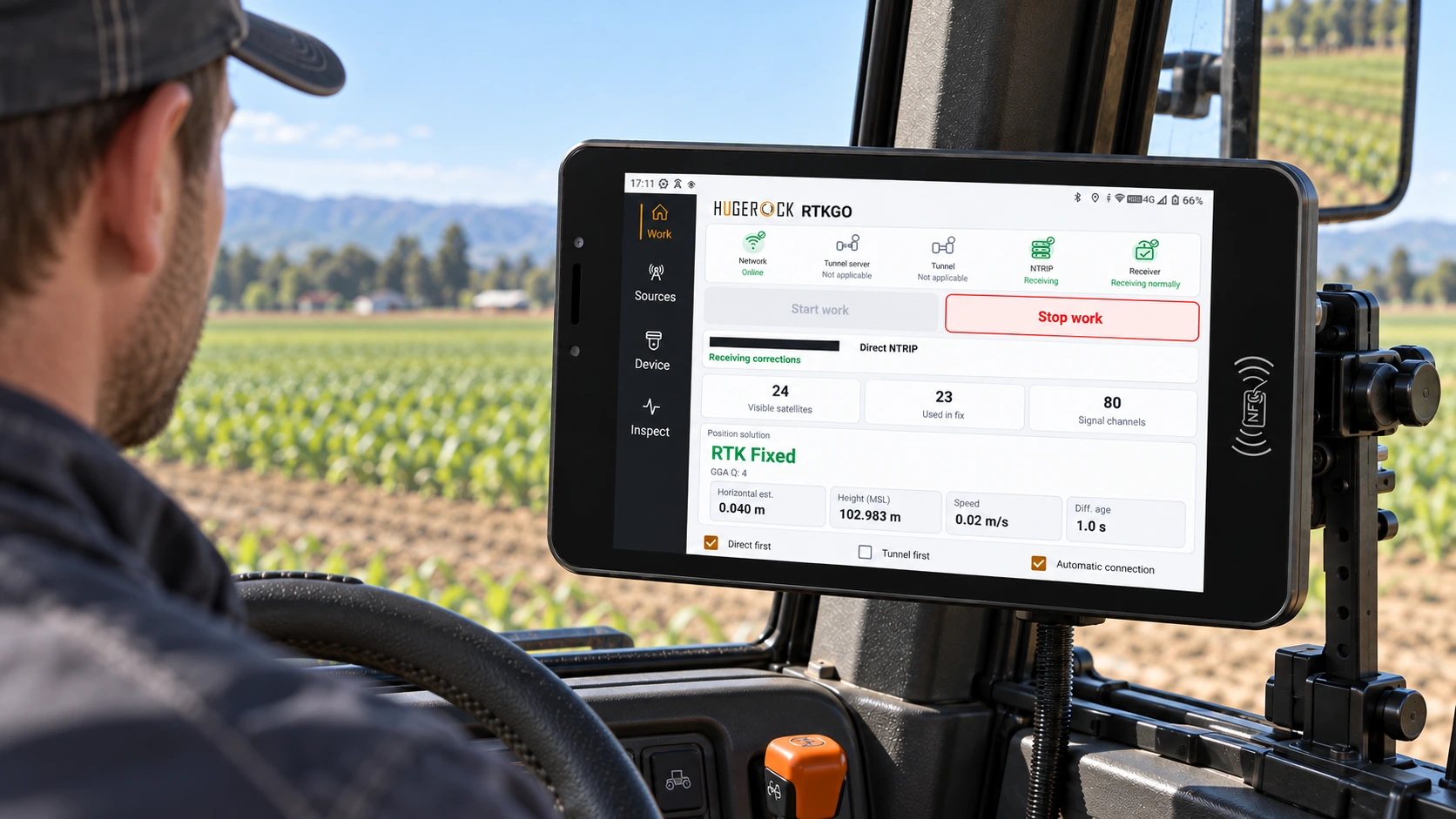
Combine an appropriate reference source with a vehicle terminal, antenna arrangement and host interface. Treat power, positioning, heading and application behavior as one integration review.
The field challenge
A successful vehicle installation depends on more than the receiver specification. Antenna geometry, cable routing, vehicle electrical conditions and the host application's data contract all need verification.
A reference-to-field architecture
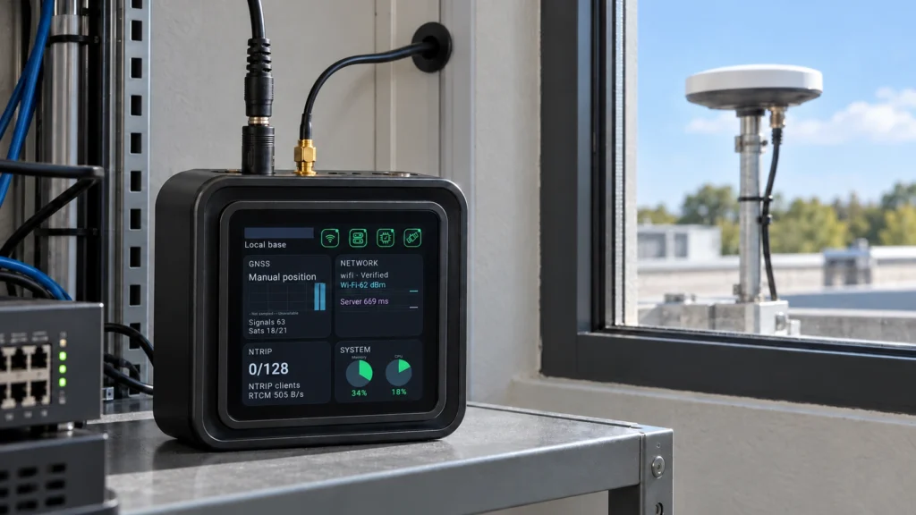
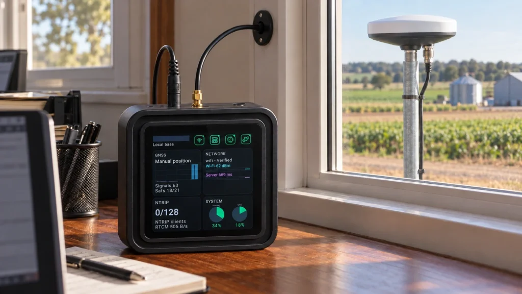
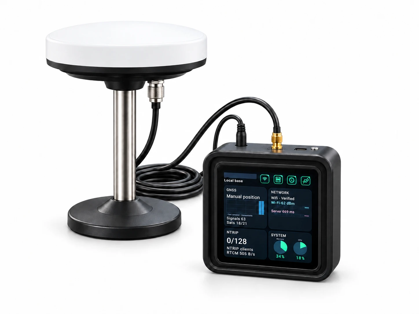
Keep the GB30 reference kit fixed at the reference site. Install GK101M in the vehicle with its separately specified vehicle antennas, protected external power and appropriate serial or Ethernet connections. Confirm the client-side NTRIP or tunnel path before acceptance.
Deployment example
The following illustrates a project workflow; it is not a report of a commissioned customer installation.
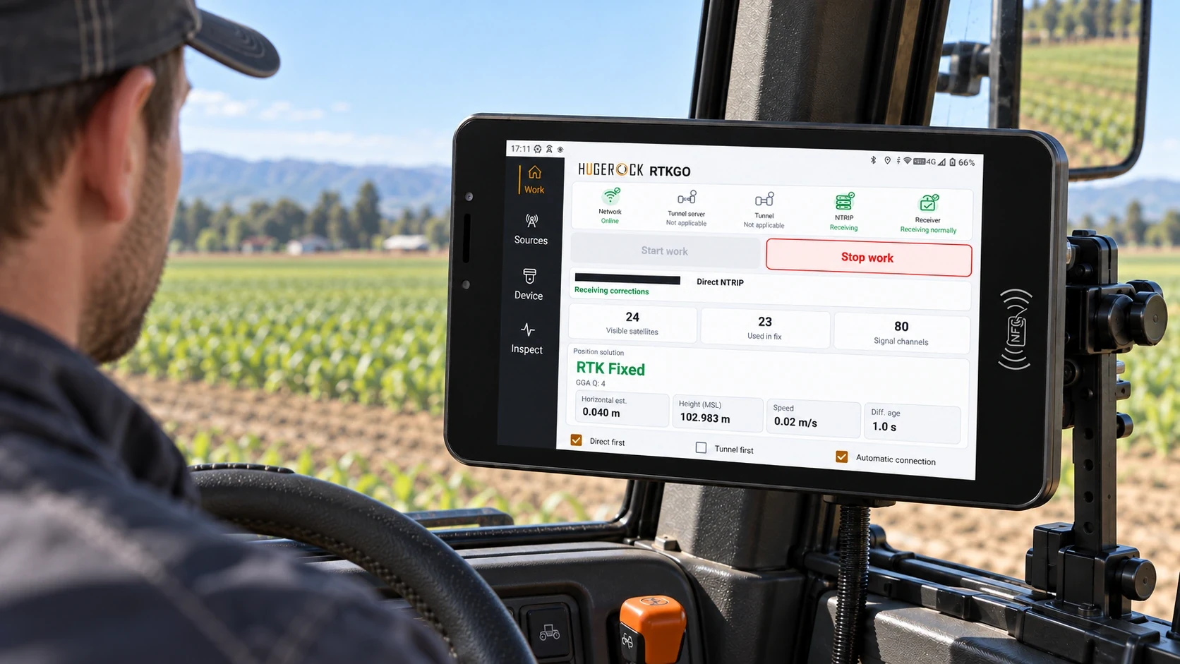
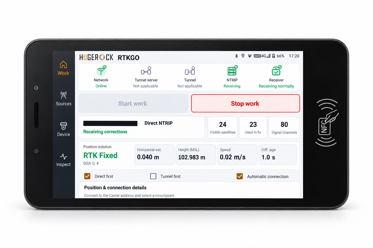
An equipment builder evaluates a cab-mounted positioning terminal for a fleet platform. GB30 supplies a fixed reference source for the trial area. A GK101M installation connects vehicle power and the required interfaces, while the integrator validates antenna placement, heading baseline and data delivery to the host application.
Define the host interface
Agree positioning and heading outputs, update requirements, interface pinouts and the application's handling of quality flags.
Design the antenna installation
Specify the antenna pair where heading is required, their orientation and baseline, cable routes and mounting stability.
Verify vehicle power
Check the external input, protection, grounding, connector retention and startup or shutdown behavior.
Test representative operation
Evaluate positioning and heading output, correction loss and recovery, data logging and host application behavior on the intended vehicle.
Acceptance and handover
• Compatible positioning and heading messages at the host interface
• Verified dual-antenna geometry where heading is required
• Protected external power and secure mechanical installation
• Documented behavior when correction data or GNSS quality degrades
Define your quotation
• Which RS232, RS485 or RJ45 interfaces and pinouts are required?
• Is positioning alone sufficient, or is dual-antenna heading required?
• What power, vibration, enclosure and mounting conditions apply to the vehicle?
Common project questions
Does GK101M use a built-in battery?
The selected GK101M configuration requires external power and has no built-in battery. Confirm its specified DC input and the complete vehicle-side power design.
What does the 0.1° heading specification depend on?
The published GK101M heading specification is 0.1° RMS at a 1m antenna baseline. Validate the actual antenna installation and operating conditions rather than applying that figure to every baseline.
Is this a complete autonomous-driving system?
No. The reference and terminal provide positioning-related infrastructure and outputs. Vehicle control, perception, functional safety and the operational system are separate integration responsibilities.
Define the vehicle installation before selecting interfaces
Does dual-antenna heading require the vehicle to move?
A dual-antenna GNSS heading system uses the relative antenna baseline rather than deriving heading only from travel direction. For GK101M, confirm receiver configuration, baseline, sky visibility and output behavior in the target installation.
What should the integration specification include?
Specify antenna locations and baseline, cabling, power protection, bracket, serial or Ethernet protocol, correction source and application acceptance tests. Confirm IP66 and the stated operating-temperature requirements against the installation design.
Related: GK101M vehicle positioning terminal · GB30 GNSS base + NTRIP Caster kit · Agricultural machinery RTK workflow