Multi-Station GNSS Reference Networks with GB30
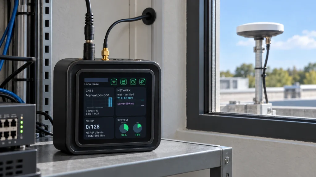
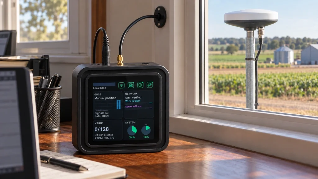
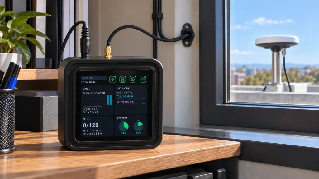
Plan a multi-site GNSS reference network with one GB30 local base and Caster plus up to eight uplink reference stations. Distribute independent local and uplink correction sources to compatible RTK clients.
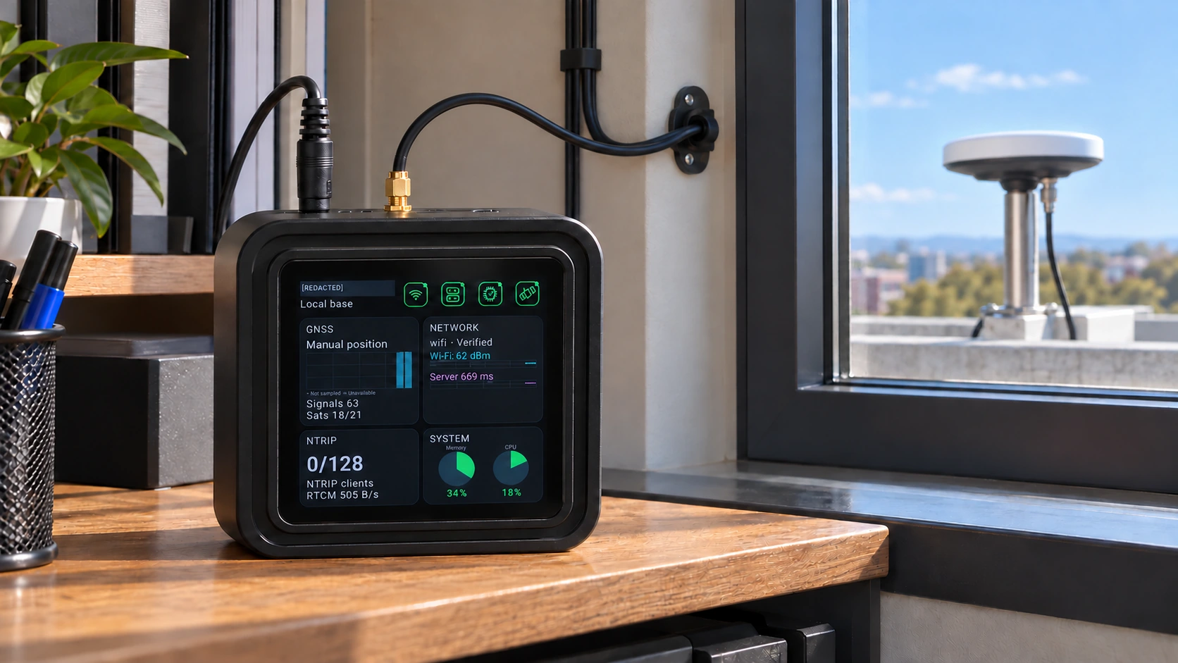
Connect multiple fixed reference points to a central GB30 in Local Base Station mode. Serve its own local source and independent uplink sources through the integrated NTRIP Caster.
The field challenge
Multiple stations need consistent reference documentation, unique source identities, reliable network paths and a clear client policy. The number of stations alone does not establish coverage or positioning accuracy.
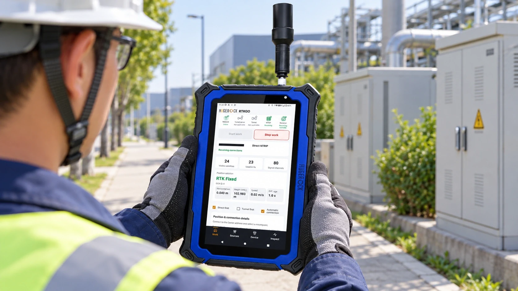
A reference-to-field architecture
The typical 8 + 1 layout uses nine complete GB30 kits: one local base / Caster and eight uplink stations. The central GB30 serves L00 plus U01–U08 as separate sources. Approximately 10km station spacing is a planning example that requires site validation.
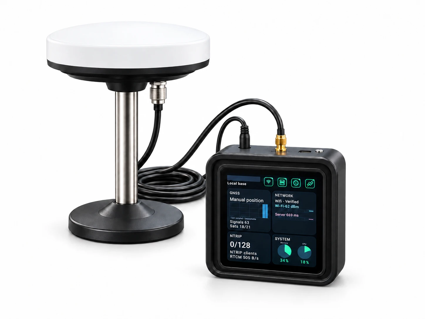
Deployment example
The following illustrates a project workflow; it is not a report of a commissioned customer installation.
A regional operator needs reference access for crews working in several districts. The operator plans a central local-mode GB30 and eight uplink-mode GB30 stations. Each site has an outdoor fixed antenna and an indoor main unit. Field teams receive the source assignment appropriate to their work area and validate it before collecting data.
Plan and document sites
Evaluate reference monuments, coordinates, sky visibility, power and network connectivity at each intended location.
Set the operating roles
Configure the central GB30 as Local Base Station + Caster. Bind each remote GB30 in Uplink mode and verify source upload.
Assign independent sources
Document mountpoints and client settings. Give field teams the suitable source for their operating area.
Accept and maintain the network
Check source activity, simultaneous clients, correction continuity and station handover records. Revalidate after reference or network changes.
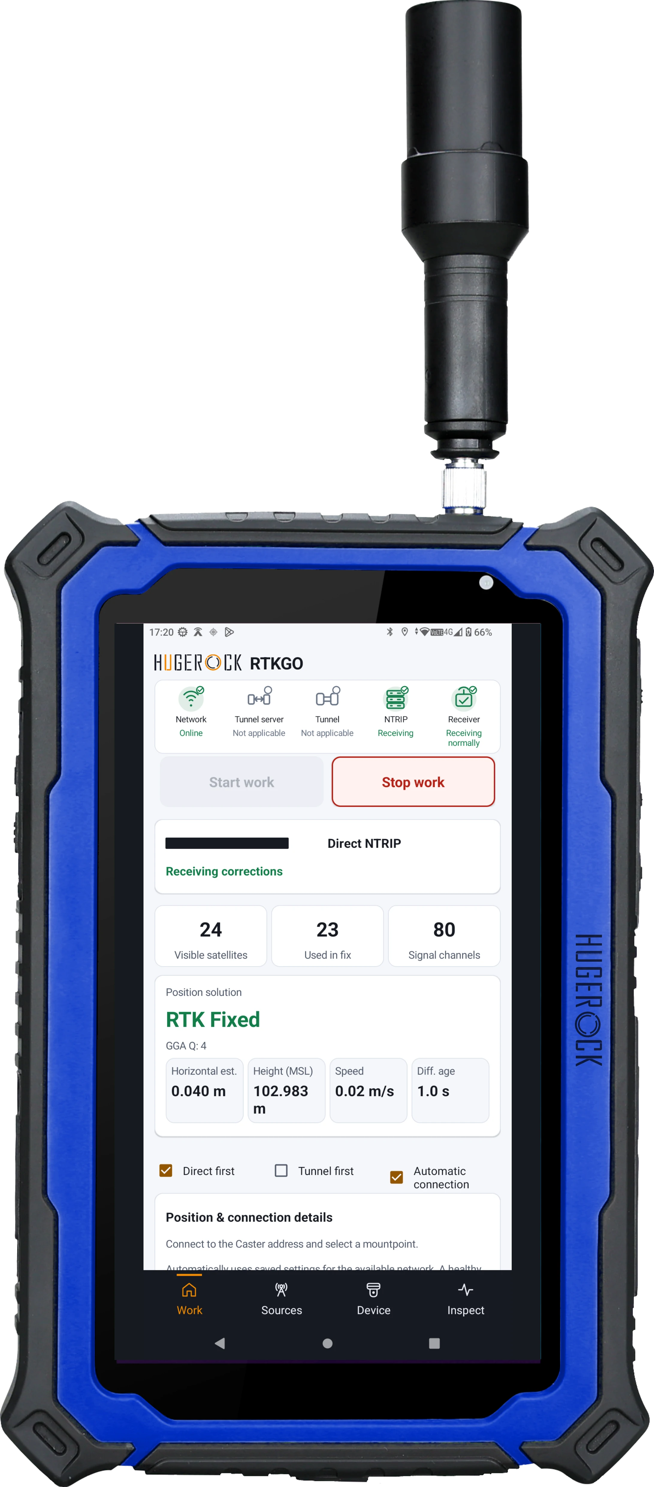
Acceptance and handover
• Accepted coordinates and installation records for every reference point
• Unique source identities and verified uplink registration
• Client access and continuity under the intended simultaneous load
• A source-assignment procedure and ongoing operational checks
Define your quotation
• How many independent reference points and work areas are needed?
• What is the expected simultaneous client count on the central Caster?
• Which locations can use direct reachability, and which need compatible tunnel access?
Common project questions
Does an 8 + 1 deployment fuse the reference sources?
No. The central GB30 makes its own source and accepted uplink sources available independently. This layout does not imply VRS, correction fusion or a network adjustment service.
Does the client automatically choose the nearest station?
Select and validate the appropriate nearby mountpoint for each work area. Manage source changes in the client configuration.
Does adding stations multiply Caster client capacity?
No. The central Caster's default is 256 client terminals with an allowance for 8 uplink stations. Up to 4,000 simultaneously online clients applies to direct NTRIP under the configured policy; the limit is not multiplied by station count.
Plan independent reference sources and client access
Does an 8 + 1 GB30 layout create a VRS network?
The central GB30 distributes its own source and eight independent uplink reference sources. This arrangement does not imply VRS generation, reference-stream fusion, automatic nearest-station selection or seamless roaming.
What area can a multi-site reference network serve?
Approximately 10km between adjacent reference points is a planning example for a distributed deployment. Actual service area depends on terrain, baseline, sky visibility, communications and the project accuracy requirements; validate it with field checks.
Related: GB30 GNSS base + NTRIP Caster kit · Fixed reference site installation · NTRIP versus tunnel access · Request a project quotation